
Application
Pembuangan Panas Materials for TIMs, Gap Fillers & Heat Spreaders
Application guide for thermal conduction, heat spreading, interface resistance, bondline control, mechanical compliance, and long-term reliability.
Jawaban singkat
For electrically insulating thermal interface materials, gap fillers, adhesives, potting compounds, or composites, start with Hexagonal Boron Nitride (hBN) or hBN x AlN (hBNxAlN). Screen Multi-Walled Carbon Nanotubes (MWCNT), GNP, or CNT x GNP (CNTxGNP), Graphene Copper (Graphene-Cu), or other conductive routes only when black color and electrical conductivity are acceptable. Validate the thermal path—bond-line thickness, contact resistance, pressure, orientation, interfaces, electrical behavior, and aging—in the finished formulation or assembly; intrinsic filler conductivity is not a system result.
What Is Pembuangan Panas in Thermal Management?
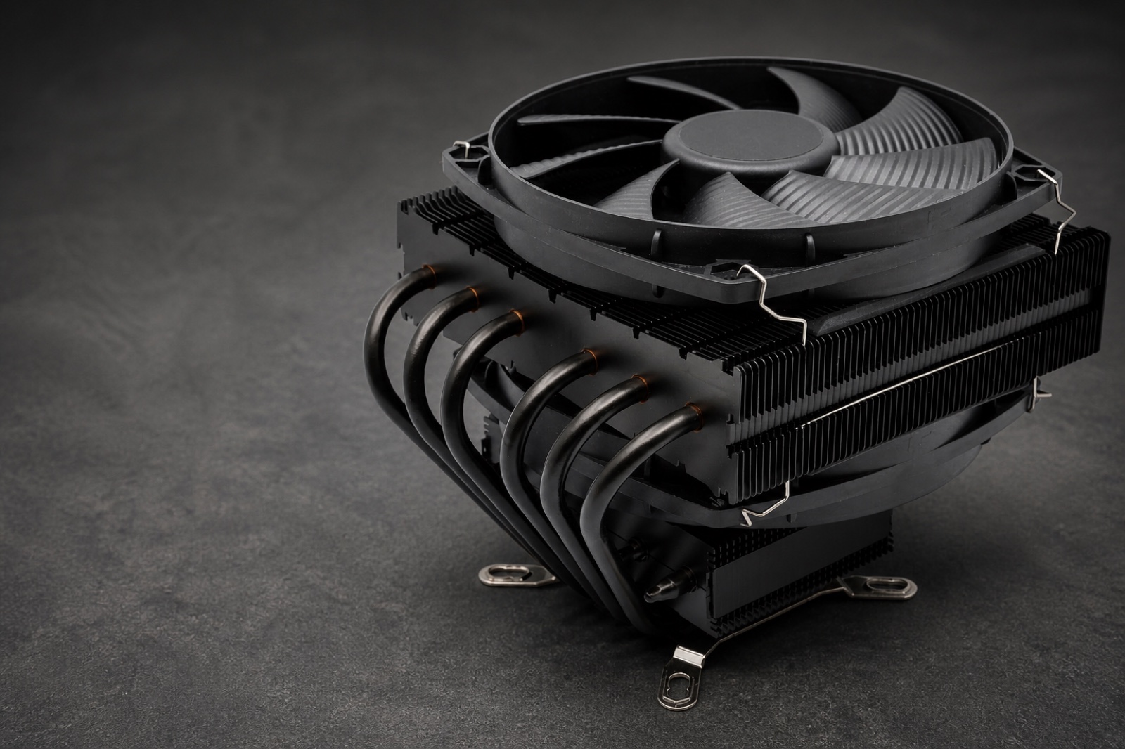
Heat dissipation is the controlled removal, spreading, or transfer of heat from a heat-generating component to a sink, housing, cold plate, substrate, or ambient environment. In real assemblies, performance is governed by the full thermal path: bulk conductivity, bond-line thickness, contact resistance, surface roughness, pressure, filler network, electrical boundary, and aging stability.
Mekanisme
Thermal pathways are constrained by contact quality, bond-line thickness, filler orientation, loading level, surface roughness, pressure, compliance, and thermal cycling. CTE mismatch can degrade contact, crack the layer, or cause pump-out over time.
The mechanism depends on the following system interfaces:
- substrate contact surface
- bondline thickness and surface wetting
- filler network and heat-flow direction
- thermal cycling environment
- mechanical pressure or stress window
Pemilihan material
Read each row as a scenario-specific route: the guidance explains why a material fits, while the rejection boundary shows when to stop screening it.
| Scenario | Materials | Guidance |
|---|---|---|
| Electrically insulating TIM, gap filler, adhesive, potting, or polymer composite | hBN / hBNxAlN | Screen hBN or hBNxAlN when thermal conductivity must improve without creating an electrically conductive path; validate bondline resistance, through-plane transport, dielectric behavior, viscosity, filler orientation, adhesion, moisture aging, and cycling stability in the final formulation. For AlN-containing routes, treat moisture/hydrolysis stability as formulation-dependent and qualify powder surface treatment, matrix compatibility, and humidity aging in the final formulation. |
| Dark conductive polymer, coating, adhesive, or heat-spreader path | MWCNT / GNP / CNTxGNP | Consider MWCNT for low-loading electrical networks, GNP for formulation-dependent in-plane spreading, and CNTxGNP for network bridging only when black color and electrical conductivity are acceptable; electrical and thermal percolation must be validated separately. |
| Experimental conductive metal-carbon coating, paste, or consolidated structure | Graphene-Cu / SWCNT-nano-Cu / SWCNT-nano-Ag | Screen metal-hybrid routes only after the final structure demonstrates in-plane and through-plane thermal behavior, density/porosity, adhesion, and humidity-bias reliability; powders alone are not finished heat spreaders. |
| Hybrid ceramic-carbon route | hBNxCNT | Screen hBNxCNT only when the project can qualify both ceramic packing and nanotube effects; do not call the final formulation insulating until dielectric strength, volume resistivity, and aged leakage are measured. |
Scope Boundary
- Heat dissipation is a full thermal path—not a single conductivity value—and this guide does not cover thermal insulation, phase-change heat storage, active cooling hardware, or resistive or photothermal heat-generation systems.
Scenarios and Subtypes
Use the host-system or subtype constraint to narrow the material direction before comparing grades or supplier data.
| Scenario | Key constraint | Material direction |
|---|---|---|
| Thermal interface material or gap filler | Minimize interface thermal resistance while keeping bondline thickness, contact pressure, pump-out, dry-out, viscosity, and electrical isolation inside the assembly window. | hBN or hBNxAlN for insulating systems; hBNxCNT only after electrical behavior is accepted. |
| Thermally conductive polymer, potting, adhesive, or coating | Balance bulk thermal conductivity with loading, viscosity, cure, adhesion, dielectric requirement, color, and mechanical retention. | hBN/hBNxAlN for insulation, MWCNT/GNP/CNTxGNP for conductive dark systems. |
| Lateral heat spreader or conductive thermal-electrical layer | Improve in-plane heat spreading or contact transport without unacceptable corrosion, migration, galvanic, or electrical-safety risk. | GNP, Graphene-Cu, SWCNT-nano-Cu, or SWCNT-nano-Ag after interface and environmental review. |
| Direct-to-chip liquid-cooled GPU/HBM package heat path | Separate solid package-stack thermal resistance from coolant, cold-plate, hydraulic, filtration, corrosion, cleanliness, and warranty requirements. | Use an approved cold-plate fluid and qualified package stack for deployment. Screen AX-DND only as a diamond-filled solid interface constituent or in a dedicated nanofluid R&D loop approved for particle loading. |
Required Thermal-Management Measurements
Compare thermal transport at the same direction, geometry, interface condition, temperature, and electrical boundary; bulk conductivity alone does not predict system heat flow.
| Metric | Target range | Unit | Kondisi | Required |
|---|---|---|---|---|
| Thermal conductivity / resistance | Report W/mK for bulk material and K·cm2/W or °C·in2/W for interface resistance under the selected thermal fixture. | W/mK; K·cm2/W; °C·in2/W | Final bondline, pressure, thickness, orientation, cure, and aging condition. | yes |
| Thermal cycling stability | Limit the increase in thermal resistance while retaining adhesion, wetting, and dimensional stability after defined hot/cold cycling. | percent or absolute thermal-resistance change; cycle count | Final assembly geometry and service temperature window. | yes |
| Rheology / process window | Inside dispensing, coating, molding, potting, or compounding limit at proposed loading. | Pa·s or mPa·s at stated temperature and shear rate | Specified shear rate and filler loading. | final qualification |
| Filler loading | Establish the wt% or vol% loading that meets the process and thermal target without unacceptable settling, voiding, or mechanical loss. | wt%; vol% | Final formulation, dispersion process, and host matrix. | final qualification |
| Electrical boundary | Define insulating, dissipative, conductive, or continuity requirement before choosing ceramic, carbon, or metal-hybrid route. | kV/mm; Ω·cm; Ω/□; continuity resistance in Ω | Final spacing, voltage, humidity, temperature, and aged state. | final qualification |
| Particle-loaded coolant compatibility | Meet the loop owner's fluid-quality, suspended-solids, filtration, hydraulic, corrosion, materials-compatibility, cleanliness, and warranty limits. | ppm suspended solids; Pa·s or mPa·s; kPa; L/min; corrosion, filtration, fouling, erosion, and compatibility results | Exact fluid formulation, particle distribution, concentration, temperature range, cold plate, CDU, tubing, seals, filters, flow rate, and aging state. | only for a separately approved nanofluid R&D loop |
Mode kegagalan
Use failure rows to identify a measurable trigger and the corresponding design response.
| Failure type | Root cause | Manifestation | Mitigation strategy |
|---|---|---|---|
| Pump-Out | Thermal cycling, CTE mismatch, pressure gradients, low yield stress, poor wetting, or unsuitable bondline geometry | Higher thermal resistance | Measure post-cycle bondline thickness, bleed, displacement, and thermal resistance before approving low-viscosity or high-compliance formulations. |
| Dry-Out | Volatilization, oil separation, oxidation, hardening, aging, or absorption into adjacent materials | Loss of wetting | Reject formulations that lose wetting or show thermal-resistance drift after thermal aging, humidity, storage, or relevant service-fluid exposure. |
| Cracking | CTE mismatch, excessive modulus, cure shrinkage, voids, weak adhesion, or thermal shock | Increased resistance, delamination, moisture ingress, dielectric loss, or intermittent contact | Validate modulus, CTE mismatch, adhesion, and crack formation after thermal shock or cycling in the final geometry. |
| Agglomeration | Poor dispersion, high filler loading, incompatible surface chemistry, insufficient shear, or re-agglomeration during storage | Viscosity spikes, nozzle blockage, surface roughness, voids, dielectric weak points, and nonuniform thermal performance | Check microscopy, particle/agglomerate distribution, viscosity curve, sedimentation, and lot-to-lot dispersion before accepting high-loading ceramic, carbon, or hybrid fillers. |
| Particle deposition, filter loading, or hydraulic drift | Unstable agglomerates, incompatible surface chemistry, excessive solids, thermal aging, unsuitable filtration, or cold-plate microchannel retention in a particle-loaded fluid study | Pressure-drop rise, reduced flow, nonuniform cooling, fouling, erosion, corrosion, contamination, or loop-service failure. | Reject a nanofluid route unless representative hardware testing shows stable hydraulics, acceptable filtration and cleanliness, compatible wetted materials, and owner/OEM approval throughout the aging interval. |
Data validasi yang diminta
| Measurement requested |
|---|
| For ASTM D5470-17(2024) reports, retain steady-state thermal-impedance data, specimen thicknesses, the apparent-conductivity calculation or linear regression, mean test temperature, pressure, preparation, and bondline conditions. |
| Record viscosity, dispensing or molding window, filler loading, and mechanical retention at the proposed formulation. |
| Test dielectric strength or volume resistivity when the heat path must remain electrically insulating. |
| Run thermal cycling, humidity, compression set, and adhesion or interface aging to confirm resistance does not drift in the final assembly. |
| For any AX-DND liquid route, provide formulation-specific particle-size and stability data plus viscosity, specific heat, thermal conductivity, pressure drop, filtration, deposition, fouling, erosion, corrosion, seal/polymer compatibility, loop cleanliness, aging, and OEM approval evidence. |
Test Methods and Reporting
| Test method | Metode | Acceptance signal |
|---|---|---|
| Bondline thermal-path confirmation | Use ASTM D5470-17(2024) for steady-state thermal impedance where applicable. For apparent conductivity, report the specimen-thickness series, linear-regression or equivalent calculation, mean test temperature, pressure, specimen preparation, bondline conditions, orientation, cure, and aged state. | Method-matched data separate bulk and contact contributions where the calculation permits, while final-assembly performance remains a separate qualification gate. |
| Process window and filler loading | Record viscosity curve, shear rate, wt% or vol%, pot life, cure, sedimentation, dispensing/coating/molding behavior, wetting, and post-process defect state. | Candidate remains manufacturable at the proposed loading without viscosity spike, filler settling, dry-out, cracking, or throughput penalty. |
| Electrical and environmental boundary | Measure dielectric strength, volume resistivity, surface resistance, or continuity before and after humidity, thermal cycling, compression, and metal-hybrid corrosion/migration exposure. | Electrical insulation or conductivity remains within the specified boundary and the aged thermal path does not drift outside the assembly target. |
| AX-DND formulation and loop qualification | Compare the exact solid-interface or nanofluid formulation with a matched control. For a fluid route, record particle and agglomerate size, stability, viscosity, specific heat, thermal conductivity, pressure drop, filtration, deposition, fouling, erosion, corrosion, wetted-material compatibility, cleanliness, and aging in representative cold-plate hardware. | The complete package and cooling loop meet the owner's thermal, hydraulic, reliability, cleanliness, serviceability, and warranty gates without relying on transferred literature results. |
Technical Basis & References
Selection evidence must match the intended heat-flow direction, specimen or bondline geometry, pressure, temperature, cure state, electrical boundary, and aging condition. Literature supports mechanism and test design; it does not establish an Aurexene Materials grade or finished-assembly claim.
- Standard Test Method for Thermal Transmission Properties of Thermally Conductive Electrical Insulation Materials ASTM International · ASTM D5470-17(2024)
Steady-state thermal impedance measurement and the thickness-series basis for apparent thermal conductivity and contact-resistance interpretation.
- Thermal Conductivity Enhancement of Polymeric Composites Using Hexagonal Boron Nitride: Design Strategies and Challenges Nanomaterials / PubMed Central · 2024
hBN anisotropy, filler orientation, dispersion, interfacial resistance, and surface-engineering considerations in polymer composites.
- Degradation Characterization of Thermal Interface Greases National Renewable Energy Laboratory · 2017
Thermal-cycling reliability context for grease displacement, cracking, voiding, and thermal-resistance drift.
- Optimizing Hydrolysis Resistance and Dispersion Characteristics via Surface Modification of Aluminum Nitride Powder Coated with PVP-b-P(St-alt-ITA) Copolymer Molecules / PubMed Central · 2022
AlN-water reaction behavior and the need to qualify material treatment and formulation stability.
- The Effect of Copper–Graphene Composite Architecture on Thermal Transport Efficiency Materials / PubMed Central · 2023
Graphene-copper architecture, processing, interface, density, and finished-composite performance constraints.
- A Review of the Interfacial Characteristics of Polymer Nanocomposites Containing Carbon Nanotubes RSC Advances / PubMed Central · 2018
CNT electrical-network formation as a matrix-, loading-, dispersion-, and morphology-dependent behavior distinct from a thermal-path claim.
- Thermal Conductivity of Graphene-Polymer Composites: Mechanisms, Properties, and Applications Polymers / PubMed Central · 2017
Graphene-composite thermal transport as dependent on loading, dispersion, morphology, interfaces, and measurement conditions.
- Confidential Computing on H100 GPUs for Secure and Trustworthy AI NVIDIA Developer · 2022
H100 package context in which the GPU and HBM3 are integrated in one package; this supports GPU/HBM package wording rather than direct coolant contact with HBM.
- DGX GB Rack Scale Systems User Guide - Hardware NVIDIA · 2026
Current rack architecture in which liquid flows through manifolds and cold plates attached to GPUs and CPUs.
- Guidelines for Using Water-Based Transfer Fluids in Single-Phase Cold-Plate-Based Liquid-Cooled Racks Open Compute Project · 2022
Water-loop fluid quality, suspended-solids, filtration, corrosion-inhibitor, monitoring, and cleanliness boundaries for conventional cold-plate systems.
- Thermal Conductivity and Viscosity of Water Based Nanodiamond (ND) Nanofluids: An Experimental Study International Communications in Heat and Mass Transfer · 2016
Formulation-specific nanodiamond-water thermal-conductivity and viscosity evidence; results do not establish AX-DND or device qualification.
- Nanodiamonds - Ethylene Glycol Nanofluids: Experimental Investigation of Fundamental Physical Properties International Journal of Heat and Mass Transfer · 2018
Formulation- and purity-dependent ethylene-glycol nanofluid behavior, including viscosity and non-Newtonian tradeoffs.
- Rheology and Thermal Conductivity of Diamond Powder-Filled Liquid Epoxy Encapsulants for Electronic Packaging IEEE Transactions on Components and Packaging Technologies · 2009
Material-class precedent for diamond-filled electronic-packaging composites while leaving AX-DND formulation and package qualification unproven.
FAQ
When should I use hBN instead of CNT or graphene?
Start with hBN or hBNxAlN when electrical insulation, dielectric strength, or a pale ceramic formulation is required. Consider CNT or graphene routes only when black color and electrical conductivity are acceptable and the final formulation validates dispersion, percolation, and heat-flow direction.
Can a thermally conductive material remain electrically insulating?
Yes. Insulating ceramic routes such as hBN and hBNxAlN can improve thermal pathways without intentionally creating an electrical network. Confirm dielectric strength and volume resistivity at final loading and again after humidity and thermal aging rather than assuming insulation from filler identity alone.
Why does high thermal conductivity not always reduce TIM temperature?
TIM temperature depends on the whole interface. Excess bond-line thickness, poor wetting, rough surfaces, insufficient pressure, voids, unfavorable filler orientation, pump-out, or dry-out can increase interface resistance even when the bulk material has a high reported thermal conductivity.
What causes TIM pump-out and dry-out?
Pump-out can result from thermal cycling, CTE mismatch, pressure gradients, poor wetting, or unsuitable viscoelastic response. Dry-out can result from volatilization, oil separation, oxidation, hardening, aging, or absorption into adjacent materials; both can raise thermal resistance over time.
What data should I request before approving a thermal filler?
Request ASTM D5470-17(2024) steady-state thermal-impedance data where applicable. If apparent thermal conductivity is reported, also request the specimen-thickness series, calculation or linear-regression result, mean test temperature, pressure, specimen preparation, and bondline conditions. Keep filler loading, viscosity at stated shear rate, electrical-boundary data, thermal-cycling and humidity-aging profiles, adhesion retention, and post-aging resistance drift with the result; the method does not by itself prove final-assembly performance.